DIY Camera Slider with Pan Head
– ESP32 Based Project
Contents:
ACKNOWLEDGEMENT
This Project Camera Slider is done by Hamza Khan and Hammad Adnan under the guidance of Dr Asim Samejo. We are thankful to you Sir for giving us your valubale time, guidance and assistance.
Futhermore, we had help of our faculity Sir Aizaz Larik, Sir Nadir Ali, Sir Farhan Shah and Sir Abid in component selcetion, 3d printing, pcb manufacturing, software analysis and enlightenment throughout the project.
OBJECTIVE
The main objective of this project is to design a Camera Slider that is not only cost affordable but also provides a smooth videography. Also to build it in a way that it should provide a stable and strong structure for use in any type environment.
INTRODUCTION
In this project we made a motorized camera slider with pan head , which is
controlled manually through a remote and wirellessly through a mobile
application(Blynk app). This is an Arduino/Esp32 based project which is 100%
DIY, built in Universities FAB(Fabrication) Lab with cheap materials like
steel pipes, basic grade 3d printer plastic and is controlled using
Arduino/ESP32, two stepper motors, potentionmeter and a joystick attached on
a custom designed PCB. Despite this, the end result is quite impressive,
with super-smooth camera moves enabling us to get professional looking
cinematic shots.
Using the controller we can either manually move the camera around or we can set start and end points and then the camera will automatically move from one to the other position. Also by changing the design of the supporting arm we can mount the slider even on a smaller tripod with additional feature of Tilt Head.
Project components
Our project inlcudes a micro controller, joystick, oled display, potentionmeter, A4988 stepper driver, nema motor(17 and 14), end-stop switch.
Micro Controller
Micro controller is a main component that conrtols our project. It works on defined instruction through programming, upon certain input it gives certain output. For micro controller we had two options either Arduino(AtMEGA 32) or ESP32(Devkit v1).Our project can be done on both controller, but for arduino we will require a wifi module for wirelless communication.In case of ESp32 it has builtin wifi module.Thus we choose ESP32.
ESP32
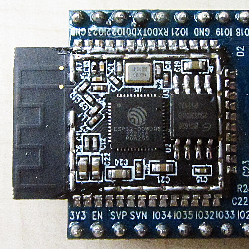
ESP32 is a low-cost System on Chip (SoC)
Microcontroller from
Espressif Systems, the developers of the famous
ESP8266 SoC. It
is a successor to ESP8266 SoC and comes in both single-core
and
dual-core variations of the Tensilica’s 32-bit Xtensa
LX6 Microprocessor with
integrated Wifi and bluetooth module.
The good thing about ESP32, like ESP8266 is its integrated RF components like Power Amplifier, Low-Noise Receive Amplifier, Antenna Switch, Filters and RF Balun. This makes designing hardware around ESP32 very easy as you require very few external components.

Specifications – ESP32 DEVKIT V1 DOIT
| Number of cores | 2 (dual core) |
| Wi-Fi | 2.4 GHz up to 150 Mbits/s |
| Bluetooth | BLE (Bluetooth Low Energy) and legacy Bluetooth |
| Architecture | 32 bits |
| Clock frequency | Up to 240 MHz |
| RAM | 512 KB |
| Pins | 30 or 36 (depends on the model) |
| Peripherals | Capacitive touch, ADC (analog to digital converter), DAC (digital to analog converter), I2C (Inter-Integrated Circuit), UART (universal asynchronous receiver/transmitter) , CAN 2.0 (Controller Area Netwokr), SPI (Serial Peripheral Interface), I2S (Integrated Inter-IC Sound), RMII (Reduced Media-Independent Interface), PWM (pulse width modulation), and more. |
These information are taken from certain websites/sources, for further knowlegde ESP32, how to use it. Check these link below.
Getting Started with the ESP32 Development Board
Getting Started with ESP32 | Introduction to ESP32
OLED 0.96' 128*164 DISPLAY
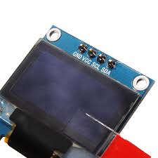
For detail and how to use Oled display.
A4988 stepper driver
At the heart of the A4988 driver you will find a chip made by Allegro MicroSystems: the A4988 DMOS Microstepping Driver with Translator and Overcurrent Protection. This integrated motor driver makes interfacing with a microcontroller super easy as you only need two pins to control both the speed and the direction of the stepper motor.
The driver has a maximum output capacity of 35 V and ± 2 A which is great for driving small to medium-sized stepper motors like a NEMA 17 bipolar stepper motor.
Nema stepper motors
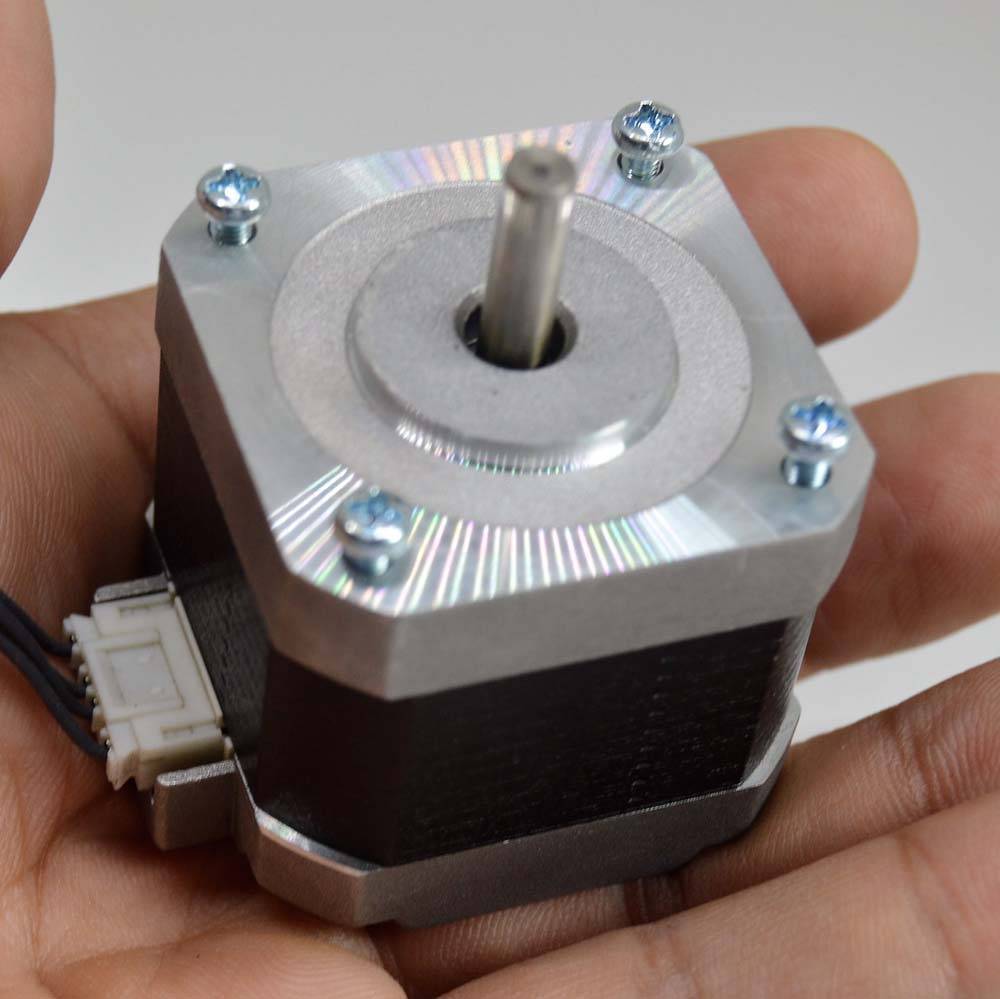
NEMA 17 Stepper Motor Technical Specifications
- Rated Voltage: 12V DC
- Current: 1.2A at 4V
- Step Angle: 1.8 deg.
- No. of Phases: 4
- Motor Length: 1.54 inches
- 4-wire, 8 inch lead
- 200 steps per revolution, 1.8 degrees
- Operating Temperature: -10 to 40 °C
- Unipolar Holding Torque: 22.2 oz-in
For more detail,
Delegation of tasks
Project Management
| TASK | DELEGATE | TIMELINE | STATUS |
|---|---|---|---|
| Literature Review | Together | Week 1 | Completed |
| Selection of Components | Hammad | Week 2 | Completed |
| Hardware Implementation | Hammad | Week 3 | Completed |
| Software Implementation | Together | Week 4 | Completed |
| Design of PCB Schematic | Hammad | Week 5 | Completed |
| PCB BOARD | Hammad | Week 6 | Completed |
| SOLDERING | Hamza | Week 7 | Completed |
| CAD DESIGN | Hammad | Week 8 | Completed |
| DOCUMENTAION | Together | Week 9 | Completed |
| TROUBLESHOOTING | Together | Week 10 (1:9) | Completed |
Intellectual Properties and Ethical Considerations
In the start of our project we did some exploration on the internet, looked
on to some projects and commercial designs. The websites which are of our use were
mentioned throughout this webpage, although these two websites have most
contribution,
1.
DIY Camera Slider with Pan and Tilt Head – Arduino Based Project
2.
Bluetooth Controlled Motorized Camera Slider
Commercialization Aspects
To begin with,
I designed the slider using a 3D modeling software Solidworks.You can find
and download this 3D model and get all dimensions from the links in the bottom
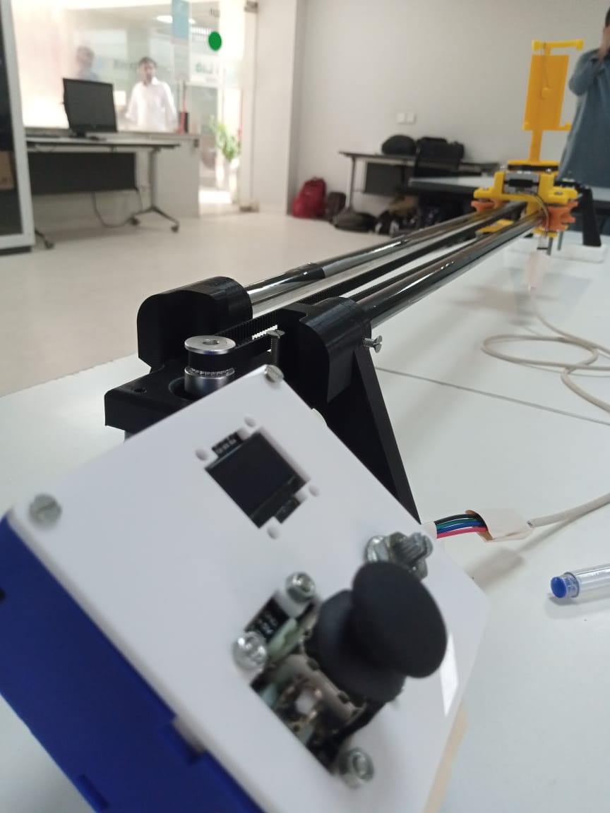
Building the camera slider
So I started with making the slider rails for which I used half inch thick steel pipes. I decided to make the slider 0.76 meter(2.5 foot) long so I cut two pieces to 0.76 meter of length. Steel pipes are light weight and inexpensive and save us from crossion.
Then I moved on with making the plastic supports on which the two pipes will be
attached. Using solidworks I designed supports for both sides, one side support
will hold nema 17 and on second part we will attach gt2 20 teeth pulley
occasionally used for nema motors.
 >
>
The dimension for first support are made according to nema 17 height and pipes diameter.This one have hole on the top side.
The second is similar to first one but this one have space for bearing to provide free movement to the pulley.This part have holes on the side for nuts.
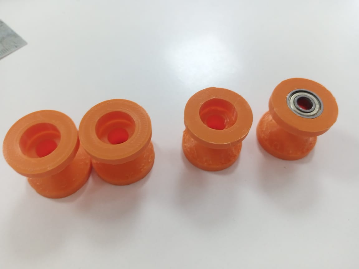
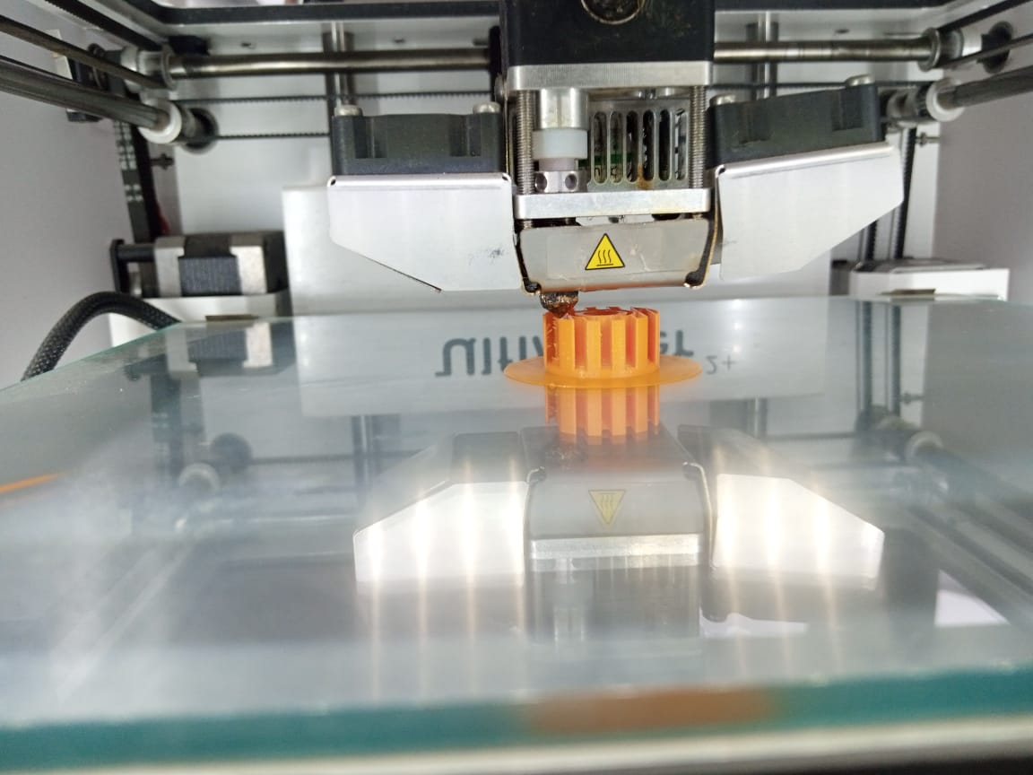
After that we needed something to roll on the pipes.For that we required u-groove pulley and to make it cost effective we made it with 3d printer. I found its dimension on the internet and changed its thickness to compensate with the plastic material we have and the availability of certain bearings sizes .
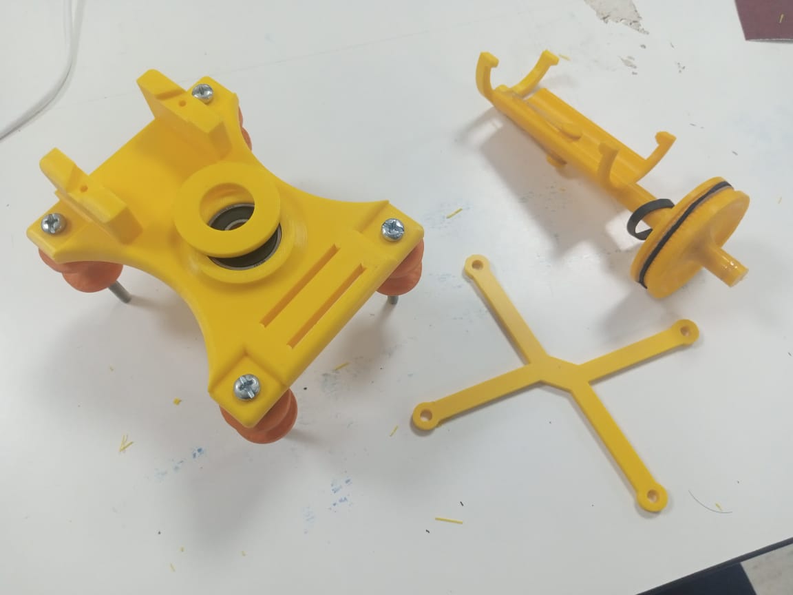
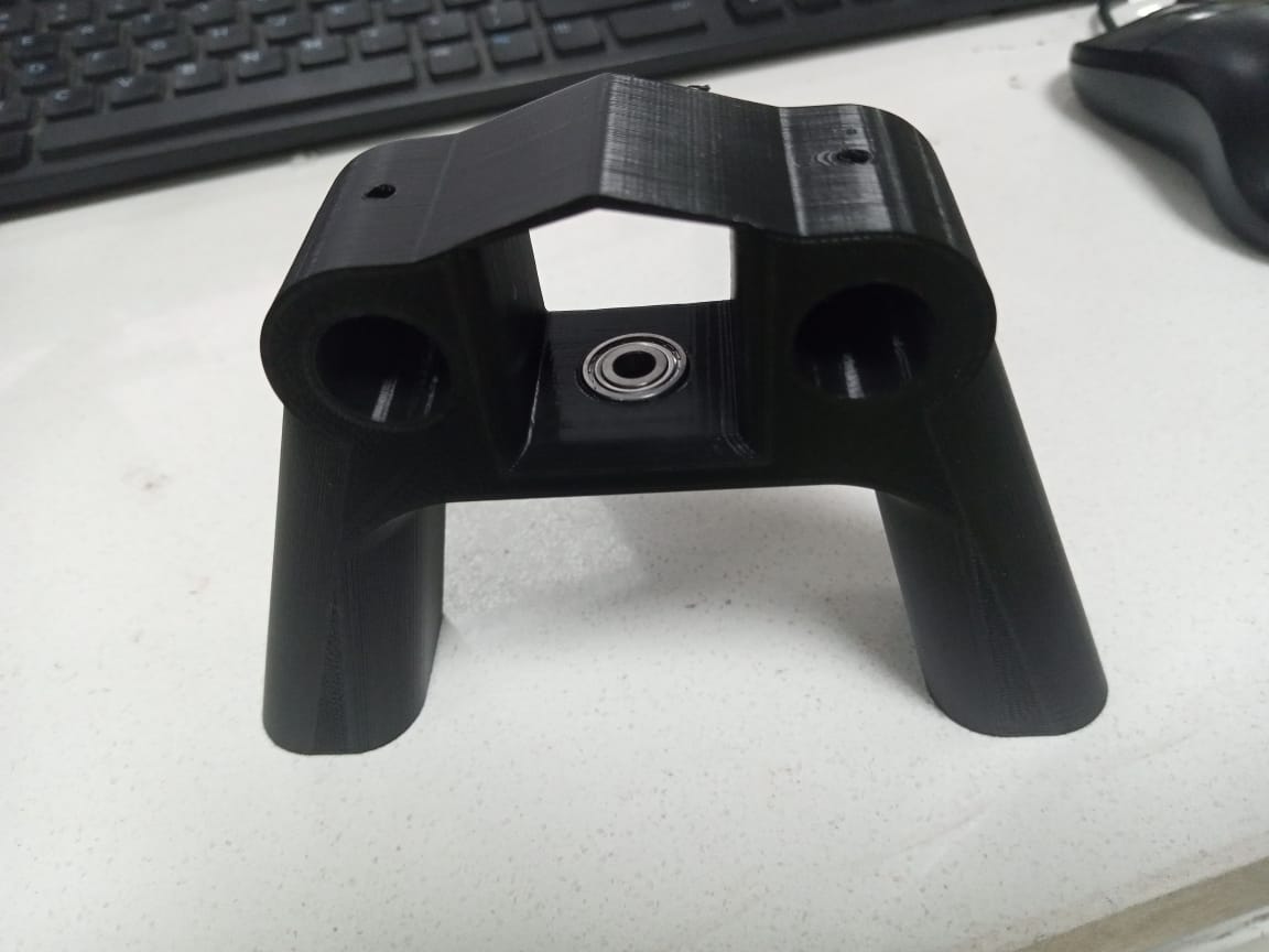
Next is the sliding platform. Again I designed it using solidworks. The design is random with some things in check.The free roll of u-groove pulley on the pipes, the grip on pipes niether to tight nor lose. Second, place for a bearing for rotating Pan head parts.Third, place for holding nema 14 to rotate pan head parts.Also a bottom part to hold pulleys.
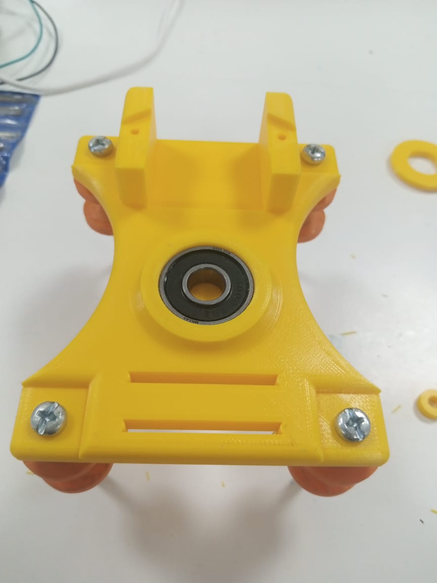
After that I designed pan head parts that consist two parts one is lower part
which has 80 teeth pulley whose dimension is taken from internet and used in our
design and it has a place for second part.The purpuse of using 80 teeth pulley
is that we can rotate mobile/camera with small motor(nema 14).The pulley will
provide torque at cost of speed(5 times speed reduction) because we are
rotating camera at a fixed slow speed.
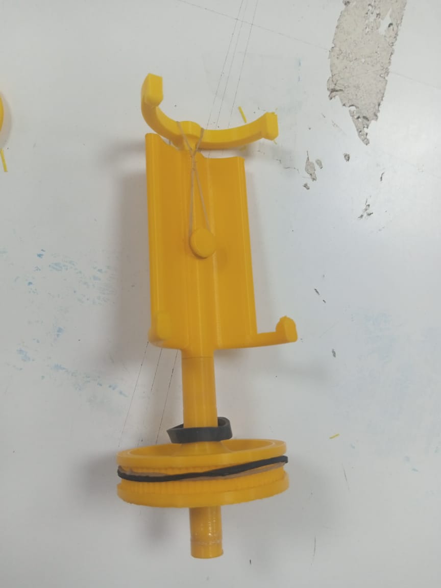
Furthermore, the second part of pan head is for holding mobile phone.Its
dimension are set for wide phone so it accumulate even thin one's.It will
have another part that is attached with a band, so that it can be arranged
accordingly.
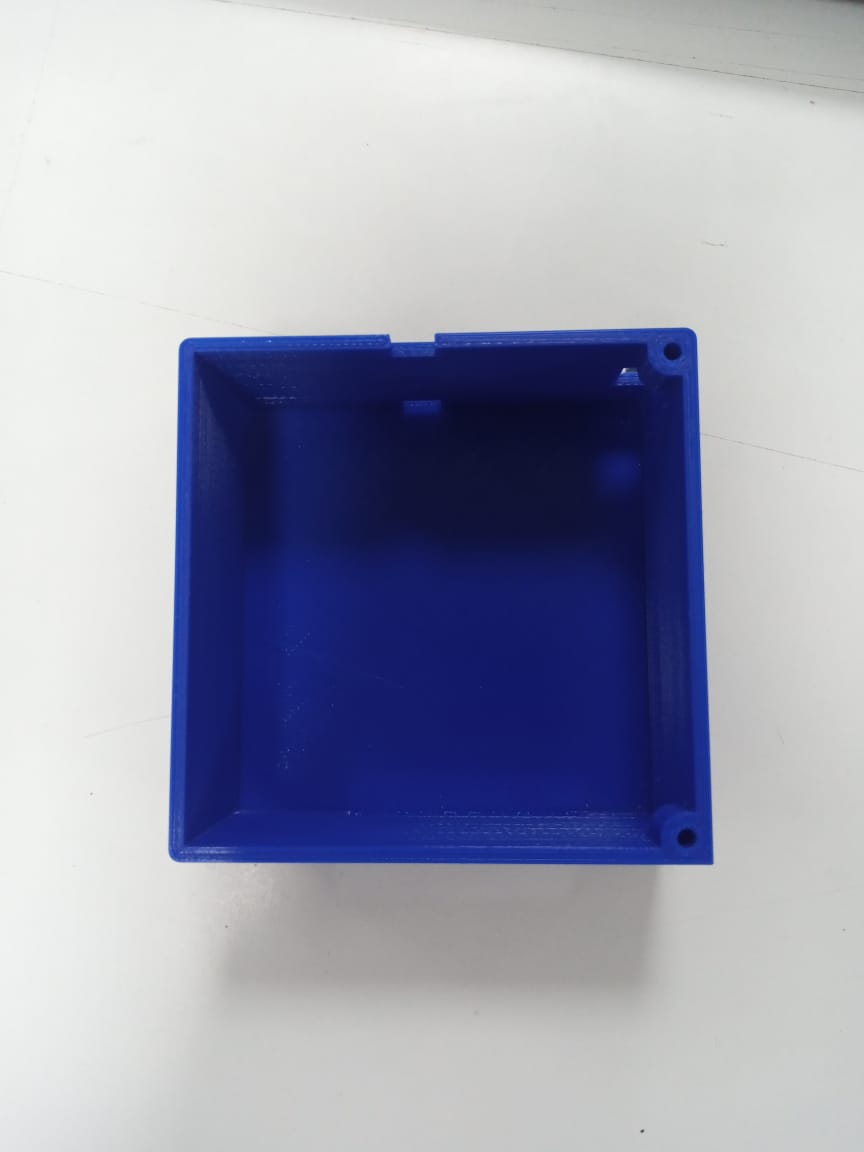
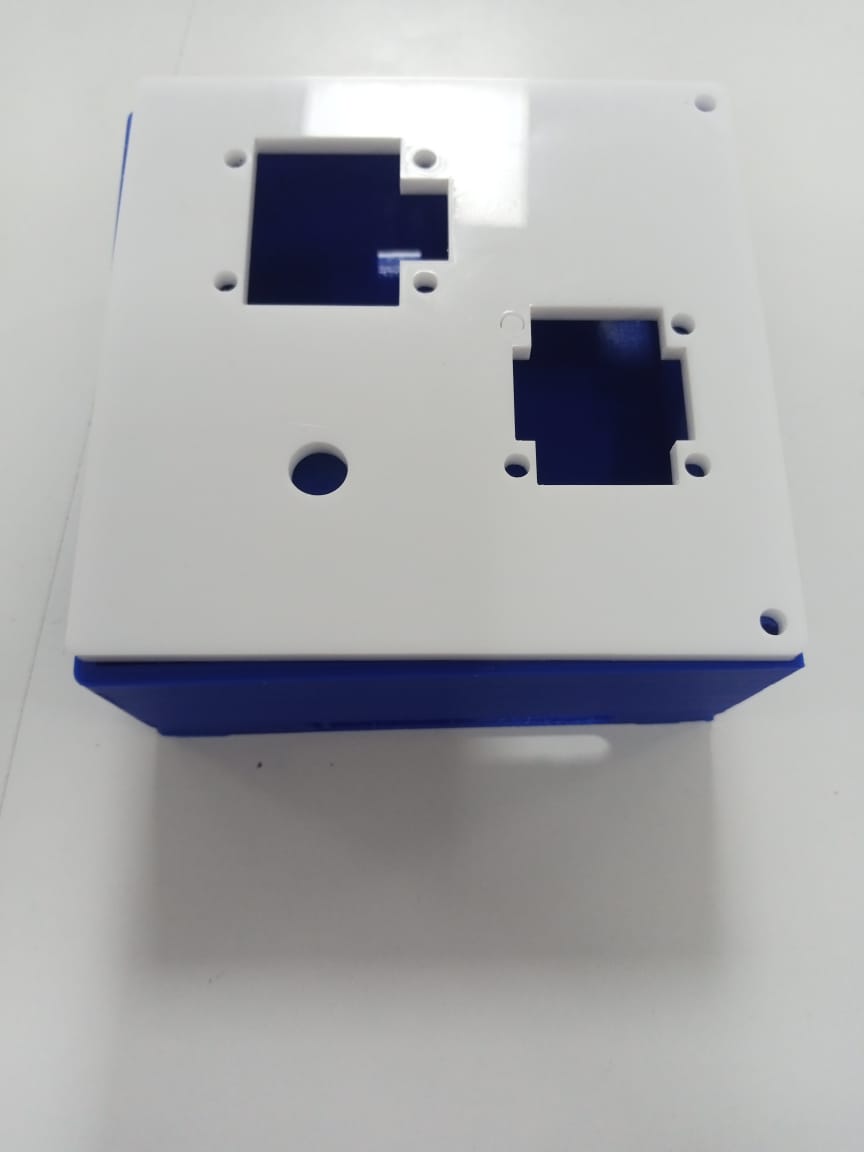
For remote, I designed a box to hold a pcb of size 3x3 inch with an opening on the side for exiting wires of nema motors.A top lid has space for joystick, oled and potentiometer and holes to attach it with box with use of nuts.
Every part assembled like stepper motor and the timing belt for the sliding platform And on the other side of the slider I secured an idler pulley so now I can install the timing belt.Using two bolts and zip ties I easily secured the timing belt to the sliding platform with every componentis placed and box part is glued to support part 1.
Circuit Diagram
Ok, next comes the fun part or installing the electronics components.
Here’s the circuit diagram of this DIY camera slider project.

So the two NEMA stepper motors are controlled via the two A4988 stepper drivers. For controlling the slider and pan movement we use a joystick connected to an analog input of the ESP32. The potentiometer is used for setting the speed of the horizontal movement.Oled will display the speed of horizontal motor. There is space connection for end stop swtiches.We can power this circuit with 9v or 12v.The 5v regulator will provide 5v to A4988 stepper driver and to the esp32.The joystick and potentiometer will have 3.3v from esp32.
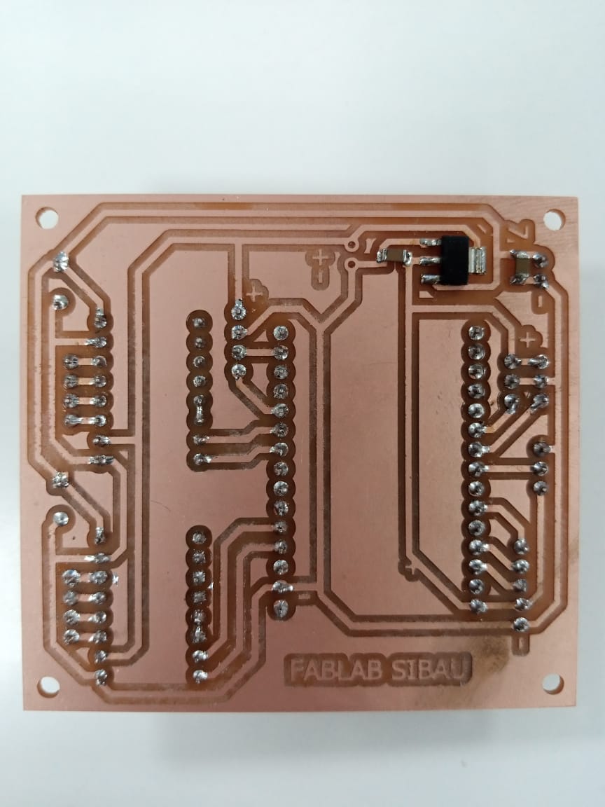
PCB Design
Next, according the circuit diagram I designed a custom PCB in order to keep the electronics components organized.DIY Camera slider PCB design
I did that using the Eagle software. The circuit had few connections, so I used only top layer and managed to get functional and good looking PCB. Once finished with this step. We had the help of our lab assistant Sir Nadir Ali to generated the files needed for manufacturing the PCB. Then the pcb is printed with in lab pcb maker. Within half hour our PCBs is made. The quality of the PCBs is great and I must admit that it is quite satisfying to have your own PCB design manufactured.
Assembling the electronics
Ok, so next I moved on with assembling the electronics components.I started by soldering pin headers PCB. This enables easier connecting and disconnecting of the components when needed. I actually used pin headers for everything except the capacitors and the 5v requlator which I soldered directly on the PCB. Furthermore, I made jumper wires for all of the electronics components connected to the lid. In this way I can easily mount the components on the controller case and at the same time connect them to the PCB. Once I had them secured I connected the components to the appropriate pin headers on the PCB. On the same panel there is also a hole through which I put jumper wires for connecting the drivers with the stepper motors, as well as the end-stop switch which I placed it at the end of the slider.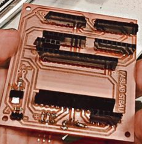
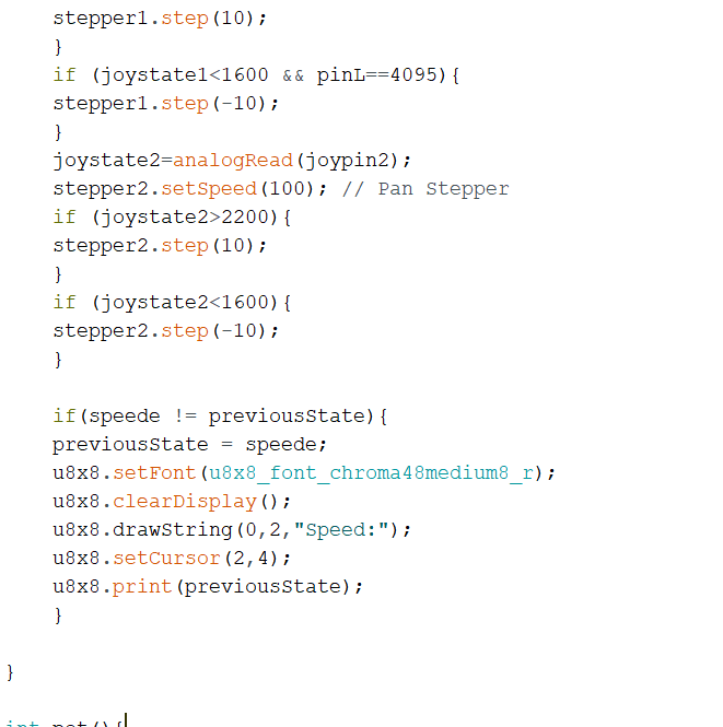
DIY Camera Slider Arduino Code
Now what’s left in this tutorial is to take a look at the Arduino code
and explain how the program works. As the code is a bit longer, for better
understanding, I will post the source code of the program in sections with
description for each section. And at the end of this article I will post
the complete source code.
The program is based on the AccelStepper library by Mike McCauley.
This is an incredible library which enables easy control of multiple
stepper motors at the same time. So once we include this library and
the MultiStepper.h library which is part of it, we need to define all
Arduino pins that going to be used, define the instances for the steppers,
as well as some variables need for the program below.
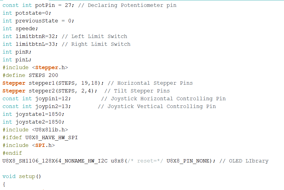
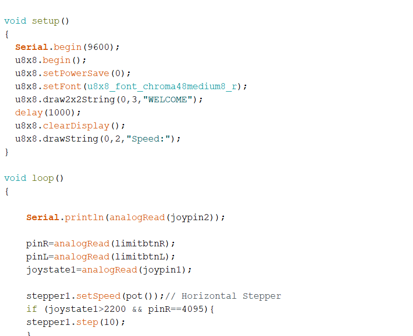
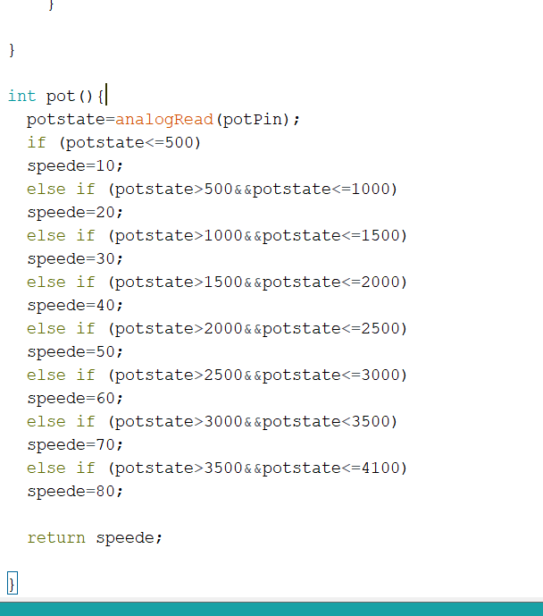
Since at first we used Arduino micro-controller to build programs for different
components like stepper, joystick, potentiometer and oled etc. Then we merged all
these segments to one program and finally converted its controls to ESP-32 for operating
our project. Snaps of final code are attatched below:
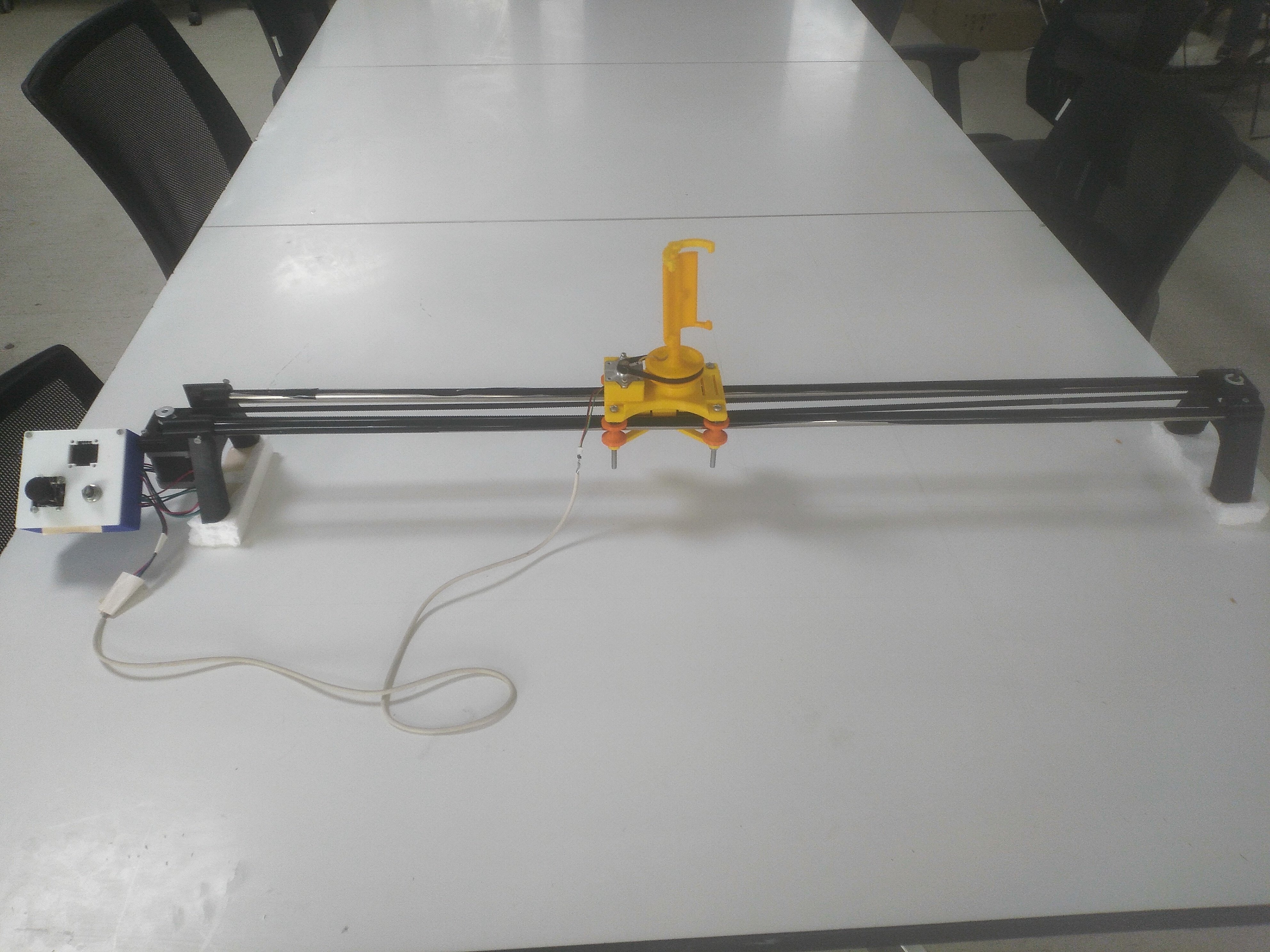
Design of finished product
Below is the final result of our project, its design and the videography done by it. A perfect smoothness of videography can be seen in the videos recorded in FABLAB. Since this was our top most priority to get a maximum smoothness and stability in our videography, so we are happy succesfully done with it.
Conclusion
In this project we learned a lot about embedded system hardware, software
and how to work them together. Besides that, we enhanced our skillset that now inlcudes
problem analysis, time management, team work and so on.
During this project we faced many problems regarding hardware and software. Furthermore we
had to remove some features due to deadline and our lack of knowledge.
Thing that we have learned,
- How to select a project which has worth.
- How to choose the components that are suitable to our needs.
- How to integrate components in a circuit.
- How to program a microcontroller to manage the components.
- How to use functions to manage our code efficiently.
- How to use interfacing protocols.
- How to use EAGLE to design a PCB.
- How to design an enclosure for a circuit using SOLIDWORKS.
- How to manage different components together in a complex circuit.
- How to troubleshoot.
- Learned about project management.
1.When we are working with A4988 it has a tendancy to shutdown for some time, that is the feature of A4988 and it also happen when you move the motor by hand when it is connected to the A4988. leave it for some time it will start working again.
2.Each microcontroller have different way in which it works, lets say for arduino when connect it with potentiometer its logic system work between 0v to 5v but in regards of ESP32 it works between 0v to 3.3v.
3.For wireless communication use with esp32 use it when it is in ap mode to avoid network delay.
4.We advise you to use remote xy app for wireless commucication cause it is easy, but for better looking application use blynk app (which uses esp32 in client server mode) it take time to program but it is versitile.